|
|
Commenting properly your C/C++ code isn’t always an easy task. Comments can be messy or they can really tell the story or translate it for people interested in the code (including you after the years). There are two types of comments programmers use in their code:
- block of comments, usually separated from the code (for example, function headers or file headers);
- inline comments, usually inserted in the code in order to explain its functionality.
This post deals with the last type — the inline comments. These comments can be either placed on a separate line, usually, before the code they intend to explain, or as a trailing comments following the lines of code that require explanation. If you are like me, coming from years of trying different programming styles and standards, you may appreciate trailing comments more — C style (/* comment */) or C++ style (// comment). My preference for trailing comments, if properly used and aligned, comes from the fact that they can tell the story “in parallel” with the code. The source becomes a two column text with the left side the code itself and with the right side the “translation” (i.e. the comments telling the story). Here is an example:
PUBLIC QUE_ITEM                 QueAdd              (PQUEUE             pque,
                                                     QUE_ITEM           pv_item)
{/* ------------------------------------------------------------------------------------------- */
    QUE_ENTER_CRITICAL ();

    if (pque->full == TRUE)                         /* if queue already full                    */
    {
        QUE_EXIT_CRITICAL ();
        return NULL;                                /* return NULL for full                     */
    }
    pque->tail = INCMOD (pque->tail, pque->size);   /* increment tail mod size                  */
    if (pque->head == pque->tail)                   /* is the queue full?                       */
    {
        pque->full = TRUE;                          /* set the indicator and                    */
        QUE_EXIT_CRITICAL ();
        return NULL;                                /* return NULL for full                     */
    }
    QUE_EXIT_CRITICAL ();
    return (pque->data[pque->tail] = pv_item);      /* return pointer to a new object           */
}
The main reason people don’t use trailing comments is related to the alignment I mentioned above. Maintaining the alignment is tedious and time consuming: when writing the code it is probably counterproductive to align the trailing comments all the time or to realign the comments after making changes to the code.
The idea of a little utility was born from this simple observation: it is easier to just add trailing comments wherever is necessary without any alignment and align them automatically at the end. Moreover, this utility program can convert C style comments to C++ style comments and vice versa performing the alignment in the same time.
Introducing TCAlign
TCAlign is a trailing comment formatting utility for C/C++ source files that has no effect on C style comment blocks (i.e. multi-line comments).
In order to preserve some inline comments, TCAlign uses a sensitivity threshold defined as the column of text from where the utility will process the comments (i.e. anything before the threshold column remains untouched). For example, if the sensitivity threshold is 25, comments beginning in columns 1-24 will remain unaffected while comments starting in a column greater or equal to 25 will be aligned and/or changed style. Obviously, if you set the threshold too low, some one line comments will be changed as well. The minimum value for the sensitivity threshold is 4 (this is to avoid touching any comments starting in the first column and meant to be used as headers for files, functions, etc.) and its default value is 25.
The user can indicate the trailing comment preferred position; by default this position is in column 65. If a source line extends beyond this position, the comment will be simply appended at the end. I recommend that you try to write your code in such a way that you will avoid extremely long one line statements by breaking them logically in more shorter lines. The code will gain in readability and will allow you adding even more meaningful trailing comments. Personally, I try to keep my code between columns 1 and 64 but some may find this too restrictive (I prefer to work with the monitor in portrait mode). Considering your typical monitor and typical text editor or IDE, you should be able to use as much as 150…160 columns (or more for wide screen monitors). Selecting a preferred position of 80 could make more sense to you.
The other important parameter is the trailing comment preferred length; by default the length is 42 characters, again derived from my own personal preference. If a comment is longer than the preferred length, the program will use it as-is. Use a larger value if you prefer long lines.
Here is the command line syntax with explanations:
TCAlign -fi <input_file> [-fo <output_file>] [options]
where the input file name (fully qualified, including path if necessary) designates a text file that would be interpreted as C/C++ source file. The output file name is optional: if missing, the utility will create a backup file before generating the output so that you have the option to revert to the original. If the output file name is indicated, the program will use it for output; don’t use the same name as the input file name or you will get an error.
The options are:
-cpp    use C++ comments style (default is C style);
-th     sensitivity threshold for trailing comments (default is 25);
-cpos   trailing comment preferred position (default is 65);
-csz    trailing comment preferred size (default is 42);
-help   this help text (other arguments are ignored).
Notes:
- make sure that 3 < th < cpos; eventually, TCAling will swap th and cpos values in an attempt to order them correctly;
- the minimum value for th, cpos and csz is 4; a smaller value will be quietly replaced with its corresponding default.
Examples:
- Align trailing comments and change their style from C to C++ style using the default parameters:
tcalign -fi acmgmt.c -fo acmgmt_fmt -cpp
- Align trailing comments and change their style from C++ to C style using a threshold column of 80 and a comment length of 50:
tcalign -fi acmgmt.c -fo acmgmt_fmt -cpos 80 -csz 50
Download TCAlign and start formatting your trailing comments. The TCAlign utility will also work for C# and other “C like” source files.
Disclaimer: TCAlign was written in less than a day and it may not be perfect. I fixed several obvious problems but I might have left something behind. If you want to contribute, the source code is available here (released under GPL). I will definitely appreciate your feedback and enhancements. I will post theme all here on this page. Thank you.
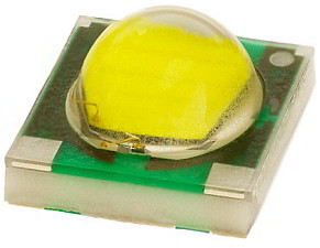 Cree® XLamp® XP-G LED Solid-State Lighting (SSL) uses semiconductor materials to convert electricity into light. Some associate SSL only with with LEDs. In reality SSL is an umbrella term encompassing different types of technologies including Light-Emitting Diodes (LEDs) and Organic Light-Emitting Diodes (OLEDs). More recently, Light Emitting Capacitors (LEC) and Light-Emitting Polymers (LEP) technologies are emerging.
While some of the technologies are evolving rapidly, LEDs are the more mature technology, particularly for white-light general illumination applications [1].
The best white LEDs are similar in efficiency to CFLs, but most of the white LEDs currently available in consumer products are only marginally more efficient than incandescent lamps. Lumens per Watt (lm/W) is the measure of how efficiently the light source is converting electricity into usable light. The best white LEDs available today can produce about 80-120 lm/W [2]. For comparison, incandescent lamps typically produce 12-15 lm/W; CFLs produce at least 50 lm/W [3].
Unlike other light sources, LEDs don’t “burn out;” they simply get dimmer over time. Although there is not yet an official industry standard defining “life” of an LED, the leading manufacturers define it as the point at which light output has decreased to 70% of initial light output. Using that definition, the best white LEDs have been found to have a useful life of around 35,000 hours (that’s four years of continuous operation). For comparison, a 75-watt incandescent light bulb lasts about 1,000 hours; a comparable CFL lasts 8,000 to 10,000 hours. LED lifetime depends greatly on operating temperature [4]. An increase in operating temperature of 10°C can cut the useful life of an LED in half; with a good thermal management, the LED life can be increased to 50,000 hours or even more (almost 6 years of continuous operation).
References:
- Light-Emitting Diode on Wikipedia
- The Most Efficient LEDs and where to get them!
- Luminous Efficacy on Wikipedia
- Philips – Understanding Power LED Lifetime Analysis
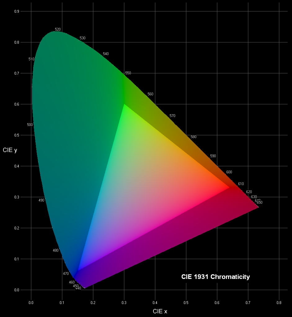 The CIE 1931 Chromaticity Diagram The CIE XYZ color space [1] defines all colors in terms of three imaginary primaries X, Y, and Z based on the human visual system that possess the following properties:
- Based on experimental data of human color matching;
- X, Y, and Z work like additive primaries RGB (every color is expressed as a mixture of X, Y, and Z);
- One of the three values – Y – represents luminance, i.e. the overall brightness (lightness) of the color as a function of wavelength;
- All color values (X and Z) are positive.
The xyY color space is derived directly from XYZ and is used to graph colors in two dimensions independent of lightness. The value Y is identical to the tristimulus value Y (in XYZ). The x and y values are called the chromaticity coordinates of the color and are computed directly from the tristimulus values XYZ. The chromaticity of a color was then specified by the two derived parameters x and y, two of the three normalized values which are functions of all three tristimulus values X, Y, and Z [2]:
  
The xyY values of colors can be plotted in a useful graph known as the CIE chromaticity diagram. Colors on the periphery of the diagram are saturated; colors become progressively desaturated and tend towards white somewhere in the middle of the plot. The point at x = y = z = 0.333 represents the white perceived from an equal-energy flat spectrum of radiation.
For any device such as a monitor or printer, we can plot its gamut – the colors that are reproducible using the device’s primaries [3]. This is one of the most common uses for the CIE diagram. The brighter triangle in the center of the plot shows the colors which can be reproduced by a standard computer screen, representing its gamut. Colors outside the triangle are said to be out-of-gamut for, and cannot be reproduced on, normal display screens. They are artificially desaturated in the plot.
For all its simple derivation from eye-response functions, the 1931 CIE chromaticity diagram is not perceptually uniform because the mathematics of xyY do not model distances between colors. This is the reason why the area of green-turquoise in the large lobe at the top left of the diagram (inaccessible to monitors) appears to be disproportionally large compared with the others. To solve this problem, other color-space coordinate systems and plots were invented – CIELUV [4], CIELAB [5] – in an attempt to be more perceptually-uniform. Their use is fairly specialized.
References:
- CIE 1931 color space on Wikipedia
- Danny Pascale — A Review of RGB Color Spaces … from xyY to R’G’B’
- Color Gamut on Wikipedia
- CIELUV color space on Wikipedia
- CIELAB color space on Wikipedia
Color perception is a brain process that starts in the eye’s cone receptors. These receptors are found in three varieties that exhibit sensitivity to approximately red, green, and blue colors. The separation between colors is not clean and there is significant overlap between the sensitivities of all three varieties, particularly between the red and green cones.
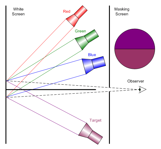
Most studies of the three-color nature of human vision are based on some variation of this simple apparatus (see the figure on the right).
One part of the screen is illuminated by a lamp of a target color; the other by a mixture of three colored lamps. Each of the lamps is called a stimulus and, in tightly controlled experiments, may consist of light of a single wavelength (monochromatic light source). The test subject (observer) adjusts the intensities of the three lamps until the mixture appears to match the target color.
Experiments have shown that certain combinations of matching colors (usually some form of the primaries red, green, and blue) allow observers to match most, but not all, target colors. However, by adding light from one of these primaries to the target color, all possible target colors can be matched. The light added to the target color can be thought of as having been subtracted from the other two primaries – thus creating the theoretical notion of a negative amount of light []. This important observation shows that the trichromatic theory cannot generate all the colors perceived by the brain. On the other hand, the trichromatic theory allows a color vision modeling process that is practical and not overwhelmingly complex. In special cases, adding a fourth color is necessary in order to cover situations where using the trichromatic model does not lead to satisfactory results.
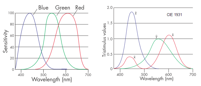 Human-Eye Cones Sensitivities and CIE 1931 Color Matching Functions In 1931, the Commission Internationale de l’Éclairage (CIE) established standards for color representation based on the physiological perception of light. They are built on a set of three color-matching functions, collectively called the Standard Observer, related to the red, green and blue cones in the eye []. They were derived by showing subjects color patches and asking them to match the color by adjusting the output of three pure (monochromatic) colors of 435.8, 546.1, and 700 nm.
Definition: A tristimulus description of a color is one that defines the color in terms of three quantities, or stimuli.
Tristimulus descriptions of color have certain advantages over spectral data: tristimulus models human vision reasonably well, and can be plotted in three dimensions. The space defined by these three axes is called color space. Colors in one color space are converted to another color space by use of a transformation. A color space is an example of a more general concept called a color model.
References:
- Color Theory on Wikipedia
- Janet Lynn Ford – Color Theory Tutorial
- Danny Pascale – Color tutorials at BabelColor
- Birren, Faber – Light, Color, and Environment, Chicago, Van Nostrand Reinhold Company, 1969
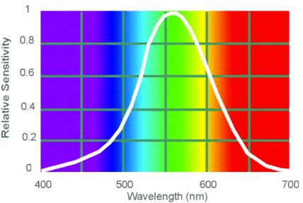 CIE Photometric Curve The human eye is an incredibly complex detector of electromagnetic radiation with wavelengths between 380 to 770 nm. The sensitivity of the eye to light varies with wavelength (see the CIE photometric curve for the day vision – V(λ) – the photopic visual response function). Photometry can be considered radiometry weighted by the visual response of the “average” human eye: 1 Watt of radiant energy at λ = 555 nm (maximum sensitivity of the eye) equals 683 lumens. The eye has different responses as a function of wavelength when it is adapted to light conditions (photopic vision) and dark conditions (scotopic vision). Photometry is typically based on the eye’s photopic response [1].
Photometric theory does not address how we perceive colors. The light being measured can be monochromatic or a combination or continuum of wavelengths; the eye’s response is determined by the CIE weighting function. This underlines a crucial point: the only difference between radiometric and photometric theory is in their units of measurement.
Here are the photometric quantities and the relationship with their radiometric counterparts:
| (Radiometric) |
Photometric |
Symbol |
Units |
| (Power) |
Luminous Flux |
λv |
lumen (lm) |
| (Intensity) |
Luminous Intensity |
Iv |
lm/sr = candela (cd) |
| (Irradiance) |
Illuminance |
Ev |
lumen/m2 = lux |
| (Excitance) |
Illuminance |
Mv |
lumen/m2 = lux |
| (Radiance) |
Luminance |
Lv |
lm/(m2 sr) = cd/m2 = nit |
Photometry example: LED radiant intensity
A specification sheet says that a red LED, with a pick wavelength of λ = 630 nm, emits Iv = 20 mcd (millicandelas). We want to know how many Watts are incident on a photodetector used to measure the light produced by the LED (need to convert photometric specification to radiometric values). Solving this problem properly requires knowing the spectral distribution of LED radiant intensity that leads to Iv = 20 mcd:

where V(λ) is the photopic visual response function and Iλ(λ) is the radiant intensity distribution [2]. In practice determining the intensity is simplified by the existence of pre-calculated tables [3].

To find total emitted flux, multiply the result by the solid angle of LED emission.
References:
- Photometry (optics) on Wikipedia
- Luminosity function on Wikipedia
- Tables of luminosity functions on UCSD Color Vision
 There are many books and papers dedicated to the study of light from different perspectives: the artist, the scientist, the designer, the historian or the biologist. There is no point in repeating here what the literature provides in abundance. The goal of this post is to introduce some concepts that will be used later in other posts so that the reader will not have to spend hours searching for basic definitions. There are many books and papers dedicated to the study of light from different perspectives: the artist, the scientist, the designer, the historian or the biologist. There is no point in repeating here what the literature provides in abundance. The goal of this post is to introduce some concepts that will be used later in other posts so that the reader will not have to spend hours searching for basic definitions.
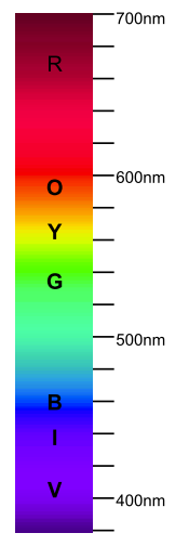
Generally speaking the light is the electromagnetic radiation within the part of the spectrum visible to the human eye: with wavelengths approximately between 400 and 700 nm [1]. There are only two ways that can affect the wavelength composition of light: emission and absorption.
The emission caused by a chemical or physical process is always related to the light source. There is no naturally occurring “perfect” white light source in the sense that the spectrum is flat (i.e. it emits the same amount of each wavelength). What the human eye perceive as white is very subjective: each of us sees a different “nuance of white”.
The absorption is the opposite of emission and happens when the light is transformed into a different form of energy.The amount of absorption of each wavelength is dependent on the nature of the object that light touches.
The reflection can be simply reduced to an absorption followed by a re-emission of the light. Usually, some wavelengths are absorbed more than others, so the light that emerges has a different wavelength composition.
Transmission can be reduced to absorption: the amount of absorption of each wavelength, and thus the intensity that emerges from the material, depends on the physical characteristics of that material. There is no such think as the perfect transmitter — only vacuum (theoretically, the absence of matter) could be one.
The light science needs a special absorptive device that converts light into electrical signals: photo sensor (or photo detector).
Colors may result:
- through the emission of certain wavelengths in different proportions;
- from white light through the absorption of certain wavelengths in different proportions.
The spectral curve of an object is its visual fingerprint, describing how the object affects light at each wavelength:
- a reflective object will be characterized by its reflectance graph;
- a transmissive object will be characterized by its transmittance graph;
- an emissive object will be characterized by its emittance graph.
 a. Reflectance Graph _____________________ b. Transmittance Graph _____________________ c. Emittance Graph
From a purely scientific point of view the spectral data is a complete and unambiguous description of color information. Unfortunately, the way our eye interprets that information is far from being objective.
The light science refers to all the aspects of light either seen as radiation characterized unequivocally by its physical parameters (like spectral data) or based on a statistical model of the human visual response to light:
- radiometry – the science of measuring light in any portion of the electromagnetic spectrum (but usually limited to infrared, visible and ultraviolet);
- photometry – the science of measuring visible light in units that are weighted according to the sensitivity of the human eye;
- colorimetry – the science of color as perceived by the human eye.
References:
- Visible spectrum on Wikipedia
- James M. Palmer; Barbara G. Grant – The Art of Radiometry (SPIE Press Book)
- Appendices section from The Art of Radiometry (above) in PDF format
- Ian Ashdown – Photometry and Radiometry – A Tour Guide for Computer Graphics Enthusiasts in PDF format
Lesson learned: the presence of an RTOS doesn’t mean you will get a better real-time performance for your application! I know, it sounds counterintuitive but this is real. A hard real-time system where the interrupts should be serviced as quickly as they come will have to rely on small and fast interrupt service routines only and not on operating system services that may be served with longer latencies. Most embedded programmers know this but in the rush of writing applications and meeting tight deadlines they forget the basic things like “keep the darn ISRs short“.
After using CoOS for few months in a relatively complex project, I must say that this kernel does a very good job for its intended target: ARM Cortex M3 processor. As I mentioned before, the CoOS kernel isn’t perfect in the sense that heavily loaded systems may experience issues like lost interrupts. After additional testing, I was surprised that more established kernels (µC/OS II, FreeRTOS) exhibit worse problems when it comes to latency related problems. As usual, these problems can be solved by designing the application differently and reducing the interrupt rate that make use of kernel services that are the most likely causes of system misbehavior.
For example, if you have a system with serial interfaces working at 115200 bps in interrupt mode, the time between interrupts coming from one UART is only ~87 µs. If the ISR involves setting a semaphore through a system call, about 1.8 µs will be added to the ISR execution time. Not to mention that the UART ISR time will add to the system timer ISR time occasionally delaying system services processing and task switches. In some circumstances this may work fine and no abnormal behavior will be observed. This may be the case when the system uses one high speed UART as the main source of rapid coming interrupts. Adding another similar UART (or maybe more) will push the system over the limits and problems like missing system timer interrupts will arise. In such cases the embedded developer can spend days looking for the source of errors.
One way to solve this problem is to avoid using any system calls (including those designed as safe for ISR use) in the interrupt service routines that are triggered by fast peripherals (e.g. SPI, I2C or UARTS at high data rates). This approach may work very well if the ISR code is short and executed quickly.
Another way is to reduce the interrupt rate by using Direct Memory Access (DMA) or hardware FIFOs if available. Most modern microcontrollers, especially in the Cortex M3 class, will give you one option or another. For example, a UART with a 16 byte FIFO operating at 115200 bps can reduce the interrupt interval to ~1.39 ms! Using higher data rates (e.g. >1 Mbps) will only be possible with the help of hardware. Remember, no RTOS kernel will enable better responsiveness for such fast occurring events — only the hardware can help.
As a rule of thumb, whenever the interrupt rate is faster than ~100 kHz, do not use the RTOS assistance at all.
While investigating the CoOS 1.12 responsiveness, I uncovered a problem in the way the kernel handles the service requests that come from user ISRs invoked by isr_Function() calls. Let’s examine first the implementation of the service request handling.
The service requests are placed synchronously in a queue that is processed either at the end of the ISR if there is no conflict with the OS (no task scheduling happening) or asynchronously in the SysTick handler when the scheduling takes place. Because in more than 90% of cases there is no conflict with the OS, the system requests are served promptly which explains why even a heavy loaded system works fine most of the time. Once a request cannot be served immediately and it is placed in the queue, the latency time increases up to one SysTick period. Assuming a SysTick every 1 ms (the minimum supported by CoOS) the response time may be too slow to accommodate the interrupt rate of a certain peripheral, the service request queue will become full quickly and the system may start missing events. One way to compensate is to increase the size of the service request queue which is 4 items by default. With enough RAM one can try 10…20 items with some hope for improvement.
Unfortunately, version 1.12 of CoOS contained a mistake in the way the service request queue was implemented: when I signaled this problem to the authors, they fixed this issue in version 1.13 which seems to function properly now. I’m sure that my solution to this problem isn’t optimal and probably violates what the authors wanted when they claimed that interrupt latency in CoOS is 0! Such a claim assumes that the interrupts will be kept enabled 100% of the time. My solution uses a short critical section that involved disabling interrupts briefly when accessing the service queue. If no system services are invoked in ISRs, the original claim stands. Not in the case isr_Function() calls are used in user ISRs. However, the penalty in latency time isn’t significant in most practical situations. I am convinced that a better implementation of the service queue management is possible using the mutual exclusion primitives that Cortex M3 provides at the machine level.
In conclusion, the current version of CoOS (1.13) seems to be stable enough for complex projects and I encourage other embedded developers to give it a try.
Please post any issues you find here and I will do my part in continuing the investigations and report my findings in the future.
One of the most delicate problems in embedded programming is to ensure that the asynchronous access to a common resource (variable, object, peripheral) does not lead the system to unpredictable behavior. When studied, the concept of mutual exclusion seems logical and perceived by most as common sense. But when it comes to implementation many programmers struggle to deal with the side effects of our “single threaded” mindset.
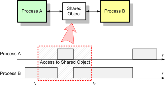
In the following picture two independent processes – A and B – compete for an object that can be accessed by both between the moments t1 and t2. The two processes can be either an interrupt and the main thread or two tasks in a multitasking environment. The conflict comes from the fact that accessing the object requires a finite amount of time that is not 0 and the moments of preemption are completely unpredictable. Some may argue that most of the time the two processes will not access the resource in the same time and the probability for conflict is almost 0. Well, “most of the time” and “is almost 0” aren’t good enough. This has to change in “all of the time” and “is always 0” in order to have a reliable and determinist system.
Another category of people may think that accessing the object is a basic CPU feature that translates into some indivisible micro-operation sequence that cannot be disturbed (i.e. interrupted). Nothing can be more mistaken. In reality, even simple operations like incrementing a counter variable may translate into more than one machine instruction. For example, process B executing:
pcom_buf->rx_count++;
if (pcom_buf->rx_count >= MAX_COUNT)
{   . . .
translates (for an ARM Cortex-M3 processor) into something like:
LDRH     R3,[R0, #+28]        ; load " pcom_buf->rx_count"
ADDS     R3,R3,#+1            ; increment its value
STRH     R3,[R0, #+28]        ; put the result back
CMP      R3,#+10              ; compare with MAX_COUNT
BCC.N    . . .
Now assume that process A (e.g. an interrupt) preempts process B (e.g. main thread) somewhere between the instructions above, and executes:
pcom_buf->rx_count--;
What will be the value of pcom_buf->rx_count seen by process B in the if test?
What the programmer expects the value of pcom_buf->rx_count should be in the if test?
Imagine that in place of a simple counter a more complex object, like our Rx FIFO, has to be shared. The number of machine instructions generated for the access will increase and the probability of conflict will increase as well.
This simple example shows why the mutual exclusion represents such an important aspect of embedded programming.
The most logical way to solve this problem is to make sure that only one process can access the shared object at one time, and this access has to be complete or atomic (indivisible). The section of code we need to protect from concurrent access is known as critical section.
As for the implementation, most programmers will disable the interrupts before the access and re-enable the interrupts when the access was done. The method works well and without significant performance penalties as long as the critical section is short and the delay introduced by this temporary interrupt disabling is reasonable. The following picture shows the result of disabling interrupts while accessing the shared object:

The result is obvious: the two processes will access the object sequentially and the process A will be delayed slightly because of process B keeping the CPU locked while the critical section is executed.
Most modern compilers have the support for manipulating the interrupt system. This support is materialized by one of the following: special macros, library functions, inline assembly code or intrinsic functions. Either one is good as long as it is used wisely. For example, GCC for ARM uses the intrinsic functions __disable_irq() and __enable_irq(), while IAR EWARM uses the intrinsic functions __disable_interrupt() and __enable_interrupt().
Let’s examine a critical section that is protected by using this method:
U8  Com_ReadRxByte  (COM_RX_BUFFER *pcom_buf)
{////////////////////////////////////////////////////////////////////////////////////////
    U8     b_val;                                  // byte holder

    __disable_interrupt ();                        // enter the critical section
    b_val = pcom_buf->rx_buf[pcom_buf->rx_head];   // extract one byte and
    pcom_buf->rx_head = (pcom_buf->rx_head + 1) %  // advance the head index and wrap
                         pcom_buf->rx_buf_size;    // around if past end of buffer
    pcom_buf->rx_count--;                          // decrement the byte counter
    __enable_interrupt ();                         // exit the critical section
    return b_val;                                  // return the extracted byte
} ///////////////////////////////////////////////////////////////////////////////////////
The statements between the functions __disable_interrupt() and __enable_interrupt() will have exclusive control of the CPU while the critical section is executed: their result is always predictable.
Is it good enough now? It is definitely better than before but still not perfect.
What happens if the caller disabled the interrupts before invoking Com_ReadRxByte()? Executing __enable_interrupt() before the return statement, Com_ReadRxByte() re-enables the interrupts unconditionally leaving the caller to think that the interrupts are still being disabled. Imagine a situation where the caller enters in its own critical section, then invokes Com_ReadRxByte(), executes few more statements after that and, finally, exits the critical section: the last part of the caller critical section remains unprotected.
There are several ways to fix this, but all have something in common: we need to know what is the status of the interrupt system before calling __disable_interrupt(). Saving the interrupt state and later restoring it solves this final problem. I will define few macros to deal with this (unfortunately, the definitions are processor and compiler dependent):
#define INTR_STAT_STOR        INTR_STAT __intr_stat__  // this is storage declaration!

#define IRQ_DISABLE_SAVE()    __intr_stat__ = __get_PRIMASK ();    \
                              __disable_interrupt ()

#define IRQ_ENABLE_RESTORE()  __set_PRIMASK (__intr_stat__)
These macros implemented in IAR EWARM 5.xx will work fine for any Cortex-M3 microcontroller. The first macro (INTR_STAT_STOR) defines a local storage of type INTR_STAT (actually U32) that will be used to save the contents of PRIMASK special register that contains the interrupt enable bit. The IRQ_DISABLE_SAVE() macro reads the PRIMASK register and store its contents in the __intr_stat__ location defined before. The IRQ_ENABLE_RESTORE() macro reloads the PRIMASK register with its saved value, restoring the interrupt status.
Now we can put everything together:
U8  Com_ReadRxByte  (COM_RX_BUFFER *pcom_buf)
{////////////////////////////////////////////////////////////////////////////////////////
    U8     b_val;                                  // byte holder
    INTR_STAT_STOR;                                // interrupt status storage

    IRQ_DISABLE_SAVE ();                           // enter the critical section
    b_val = pcom_buf->rx_buf[pcom_buf->rx_head];   // extract one byte and
    pcom_buf->rx_head = (pcom_buf->rx_head + 1) %  // advance the head index and wrap
                         pcom_buf->rx_buf_size;    // around if past end of buffer
    pcom_buf->rx_count--;                          // decrement the byte counter
    IRQ_ENABLE_RESTORE ();                         // exit the critical section
    return b_val;                                  // return the extracted byte
} ///////////////////////////////////////////////////////////////////////////////////////
We will return to the problem of mutual exclusion later in the context of a real-time multitasking environment. In the mean time, try to put everything to work in your projects and post your comments or questions here. Good luck!
Today I will modify the code to support FIFO empty/full checking. Having the rx_counter to keep track of the actual content of the buffer it will make this task easy:
BOOL Com_IsRxBufEmpty (COM_RX_BUFFER *pcom_buf)
{////////////////////////////////////////////////////////////////////////////////////////
    return (pcom_buf->rx_count == 0);               // return TRUE if empty
} ///////////////////////////////////////////////////////////////////////////////////////

BOOL Com_IsRxBufFull (COM_RX_BUFFER *pcom_buf)
{////////////////////////////////////////////////////////////////////////////////////////
    return (pcom_buf->rx_count >= pcom_buf->rx_buf_size);   // return TRUE if full
} ///////////////////////////////////////////////////////////////////////////////////////
Or, if you like, write them as macros:
#define Com_IsRxBufEmpty(pcb)  (pcb->rx_count == 0)
#define Com_IsRxBufFull(pcb)   (pcb->rx_count >= pcb->rx_buf_size)
(we will talk more about when to use macros vs. when to use functions).
Now we have the ability to handle the situations where knowing if the FIFO is full or empty is important.
For example, in the Com_ISR() function, if the FIFO is full and characters continue to come, one decision may be to drop them (in place of overwriting the buffer):
void  Com_ISR  (void)                       // USART Rx handler (ISR)
{////////////////////////////////////////////////////////////////////////////////////////
    COM_RX_BUFFER *pcom_buf;                // pointer to COM buffer
    U8             b_char;                  // byte holder

    // . . . . . .                          // identify the interrupt
    pcom_buf = Com_GetBufPtr (USART1);      // obtain the pointer to the circular buffer
    // . . . . . .                          // do other things as required
    b_char = USART_ReceiveData (USART1);    // get one byte from USART1
    if (!Com_IsRxBufFull (pcom_buf))        // if FIFO buffer not full
    {
        Com_WriteRxBuf (pcom_buf, b_char);  // write the byte into the circular buffer
    }
    // . . . . . .                          // do other things as required
} ///////////////////////////////////////////////////////////////////////////////////////
I’m not going to argue about this way of solving the FIFO overrun situation over another solution – the programmer who knows the application can decide what is the best way to handle this.
In the case of ComGetChar(), the attempt to extract a byte from a FIFO that is empty will lead, most likely, to waiting. Let’s imagine for a moment that we have the ability to delay the code execution for a number of milliseconds. The parameter timeout will indicate the amount of time the function will wait for a character to arrive before returning with an error code. Be aware that I do not say how the delay is actually implemented (in some cases the delay can be invoked by a system function call, if available):
S32   ComGetChar   (U32 timeout)            // the "GetChar()" function
{////////////////////////////////////////////////////////////////////////////////////////
    COM_RX_BUFFER *pcom_buf;                // pointer to COM buffer
    U8             b_val;                   // byte holder

    pcom_buf = Com_GetBufPtr (USART1);      // obtain the pointer to the circular buffer
    // . . . . . .                          // do other things as required
    while (Com_IsRxBufEmpty (pcom_buf))     // as long as the FIFO is empty
    {
        if (timeout == 0)                   // if time is out
        {
            return (-1);                    // return -1 as error code
        }
        else                                // otherwise
        {
            timeout--;                      // update the delay counter
        }
        DelayMilliseconds (1);              // delay one millisecond and wait more
    }
    b_val = Com_ReadRxByte (pcom_buf);      // extract character from the circular buffer
    return (S32)b_val & 0xFF;               // return character as a 32-bit signed int
} ///////////////////////////////////////////////////////////////////////////////////////
Essentially, when the FIFO is empty, the execution will stall for timeout milliseconds. The caller should be aware of this. In the context of a multi-tasking environment, delaying (or looping for long times), in the right conditions, will not stop other tasks to be executed. However, in a simple foreground/background environment where the CPU executes one thread that may only be interrupted by ISR execution, waiting can freeze the application.
There are many ways of avoiding this active waiting.
- The easiest way is to check the FIFO status before invoking ComGetChar(): if there are characters, the function can be called without time penalty: if not, the program can continue on a different path (assuming the data is not temporarily needed). This is also the essence of cooperative multi-tasking: when one thread reaches the point where it has to wait it yields control to a different thread and when that thread needs to wait the yield process continues. Cooperative multi-tasking can be implemented in many ways: state machines, co-routines, etc.
- Another way is to use a preemptive multi-tasking approach where the tasks are interrupted from time to time (even when no I/O is involved) and executed according to a pre-established CPU sharing policy. This way no task can freeze the entire system while waiting for data or an event to happen. What a modern preemptive RTOS does is just this – it multiplexes the CPU based on a certain policy involving priorities, time sharing and cooperative primitives. But this is a much longer discussion…
In the following post I will return to the mutual exclusion problem in the context of the simple situation of a single tasking with interrupts (or foreground/background) programming environment. Have patience and post your comments here!
Studying the implementation of the FIFO buffer from my previous posting some may have realized already that the code does not address few important things:
- The example does not give the reader any indication where the buffer is actually allocated and how and when this allocation is done.
- There is no check if the FIFO buffer is empty (in ComGetChar) or full (in Com_ISR) – the rx_counter is not used anywhere to detect such conditions despite of the declared intention of making it the holder of the actual number of bytes in the FIFO.
- There is no mutual exclusion mechanism in place to prevent concurrent access to either the buffer itself or to the rx_counter that is, you heard it right, just another shared resource requiring protection.
Judging by the way the FIFO data structure was declared, the buffer itself is not allocated statically when a variable of COM_RX_BUFFER type is defined. We need either a pre-allocated buffer of a given size or a dynamically allocated piece of memory to initialize the rx_buf pointer. I think the best idea is to let the caller perform these operations, offering just the right means to do it.
The easiest way is to declare some storage area, statically allocated, and have a function to perform the initialization. The user must write something like:
#define RX_BUFFER_SIZE       128

U8      MyRxStorage[RX_BUFFER_SIZE];

void MyFunction  (void)                     // user function
{////////////////////////////////////////////////////////////////////////////////////////
    // . . . . . .                          // code that does not require serial I/O
    ComRxBufInit (MyRxStorage,              // initialize the Rx FIFO before
                  RX_BUFFER_SIZE);          // using it later in the function
    // . . . . . .
    UserChar = ComGetChar (1000);           // now you can read one byte
    // . . . . . .                          // do other things as required
} ///////////////////////////////////////////////////////////////////////////////////////
In the case of dynamically allocated memory, you will have to obtain the buffer by calling:
MyRxStorage = malloc (RX_BUFFER_SIZE);
and declaring MyRxStorage as a pointer not as an array. But I’m against using dynamic allocation in embedded programming. Keep an eye on my blog and… one day I will tell you why.
The function ComRxBufInit() will look like the one below:
void  ComRxBufInit  (U8 *pbuff, U32 size)   // Initialize the Rx FIFO structure
{///|///////////////////////////////////////|////////////////////////////////////////////
    COM_RX_BUFFER *pcom_buf;                // pointer to COM buffer

    pcom_buf = Com_GetBufPtr (USART1);      // obtain the pointer to the circular buffer
    pcom_buf->rx_buf = pbuff;               // store the FIFO buffer pointer
    pcom_buf->rx_buf_size = size;           // and its size
    pcom_buf->rx_count = 0;                 // reset the byte counter
    pcom_buf->rx_head = 0;                  // and the head
    pcom_buf->rx_tail = 0;                  // and tail pointers
    // . . . . . .                          // do other initialization things
 } ///////////////////////////////////////////////////////////////////////////////////////
As a side note, the function Com_GetBufPtr() was implemented to help the programmer to expand the code for more than one serial interface. In the end of my series of posts dedicated to this subject I will offer a fully functional code that will be able to handle any number of serial interfaces – the only part the programmer should be providing would be the lower layer that give access to the USART registers and the hardware initialization required by the MCU (I/O pins, baud rate, etc.)
I know this looks to many like a never ending story. Believe me, it has an ending or, even better, a happy ending. Stay tuned.
|
|


